GPS
Measurement of Aircraft Glide Ratio
Scott Kurowski, Plus
One Flyers member, 12/18/2006
While working on a ditch-risk analysis for flights
to Catalina Island (AVX) I wondered how reliable the POH glide ratio that I had
been using for years might really be.
Ditching at sea in fixed-gear aircraft is a highly unfavorable forced
landing. As a relative confidence
benchmark (and to have yet another reason to go flying) I decided to
empirically determine typical engine-idle glide ratios in a few aircraft
I regularly flew, and performed without any particularly finely-tuned
technique. Below are my methods and
findings using a portable Garmin GPSMap
296.
By flying a square box and measuring the GPS
ground speeds at a uniform IAS on at least three headings 90o apart,
TAS and wind can be mathematically determined and the wind nullified for glide
ratio. In the vector parallelogram (figure 1) below, the fourth leg along 090
is omitted for clarity. The resultant vectors g1-g4 are the measured GPS ground speeds for each compass quadrant
heading, w is wind speed, and a is aircraft TAS.
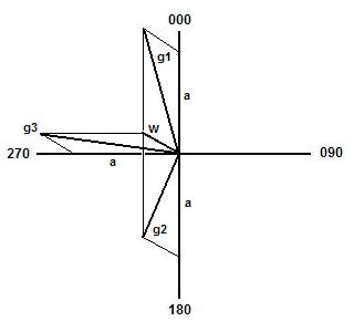
Figure
1 – Vector Parallelogram for GPS Wind and True Airspeed Computations
The formulae below can be derived [references 2,3]
from the above vector parallelogram figure.
|
|
|
|
|
|
|
|
|
|
|
TAS |
Wind Speed |
Wind Direction using g3 |
Wind Direction using g4 |
|
|
|
|
|
The C-172N manual diagram gives a 9.1 glide ratio
[1]. To test this in a controlled setting I flew out with a friend to the
desert east of
We determined that hand-recorded measurements from
the GPS unit’s screen worked well enough in cases, but it was far better to
simply hand-record the GPS unit’s timestamps of the various measurement events
on a printed form for the measurement plan, and let the GPS unit capture our
data for us.
After the flights I downloaded the detailed GPS
track data log from the GPS unit [6] and loaded it into a spreadsheet [8] to
time-weight average measured box leg data, compute the true and magnetic
courses and vertical airspeeds as differentials of each sequential pair of GPS
data records at relative times t+1 and t, and finally compute
the glide ratios.
As an example of time-weighted averaging, two GPS
data records having ALT = 7200 MSL for TP SEC = 20 seconds and ALT = 7250 MSL
for TP SEC = 10 seconds, using
results in an average altitude of (7200 x 20 + 7250 x 10)
/ (20 + 10) = 7217 MSL for the combined 30 second interval.
For two nearby positions away from polar
latitudes, true course and magnetic course very closely approximate
TC t+1 = arctan( ( LATITUDE t+1 – LATITUDE t )
/ ( LONGITUDE t+1 – LONGITUDE t ) ) – 90o ,
MC t+1 = TC t+1 +
VAR , using local VAR = –13.13o
.
I used the hand-recorded data to identify the GPS
data records for each leg of each box and verified the derived Montgomery Field
(MYF) arrival and departure magnetic courses were 280o as
expected. The figures for the GPS VSI FPM
rate of descent for glide boxes are altitude differentials for GPS data given
by
GPS VSI FPM t+1 = ( ALTITUDE t+1 – ALTITUDE t ) / ( time
t+1 – time t ) .
The figure for GPS ALT FPM gross rate of descent
is similarly computed from the starting and ending GPS-recorded altitudes and
times of straight glide. The GPS unit
apparently records the altitude at the end of the data record time snapshot, so
the time point interval TP SEC of the starting altitude record is excluded from
the time total for the GPS ALT FPM differential.
Measurement #1 – N6360D
N6360D is a 160HP C-172N with 50 gallon fuel tanks
and a maximum GTW of 2300 lbs.
Approximate weight at the time of data collection was 2200 lbs. The C-172N manual gives Vg = 65 KTS IAS for
GTW 2300 lbs. According to Kershner [7], Vg as a function of Vg0 at
maximum GTW WM for an aircraft at weight W is given as
![]() ,
,
for
which Vg = 64 KTS but I used 65 KTS. The
glide ratio determination method I used first measures GPS ground speeds in a level
flight box along each compass quadrant holding a uniform IAS, then measures the
GPS ground speed and descent rate of a glide to a specific waypoint (figure 2).
L08 AWOS reported 30.46 and 16C/-12C. After
temporarily checking the altimeter reading at 29.92 and the OAT at 45F, the
cockpit density-corrected TAS reading was about 115 KTS. For the first step, we stayed at 9500 MSL and
100 KTS IAS as we measured the GPS ground speed along each of the four headings
of 000, 270, 180 and 090. Only three such legs are needed but a fourth should
reduce any systematic errors.
To measure the glide, I punched in L08 as my
Direct-To waypoint and selected a steady heading – in this test case, 052o
according to the panel gyro compass – that resulted in our flight path crossing
L08 in the GPS unit display. At panel
altimeter 8500 MSL and IAS Vg = 65 KTS, we glided until the GPS read a distance
of 0 NM to L08. I noted a panel VSI rate of just over –650 FPM during the
glide. We then climbed back to 8500 MSL
and repeated the glide from a different direction, gyro heading 325o.
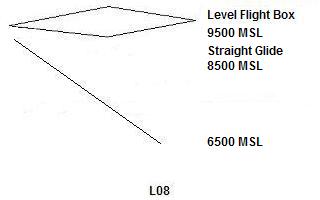
Figure 2 – N6360D Straight Glide
Measurement Flight Path
The time-weight averaged level flight box GPS data
and derived values are compiled in Table 1.
Time-weighted averages are given in bold
font for ALT, ALT FPM and VSI FPM using the summed total TP SEC time as the
weight in underscored italic
font, at the bases of their columns.
|
|
||||||||||||||||||||||||||||||||||||||||||||||||||||||||||||||||||||
|
Table 1 – N6360D Level Flight Box Data |
|||||||||||||||||||||||||||||||||||||||||||||||||||||||||||||||||||||
Using the g4 value to check for consistency should
produce very similar results as does using g3, and here the computed values
closely agree with each other and with the cockpit TAS estimate. The wind was determined to be 096o
at 14 KTS.
The glide magnetic course computed using the GPS
data records differential method for the glide start and end points was MC =
45.3o and the ground speed using time-weighted averaging was GS =
56.0 KTS. Using the cosine law [3] for
the wind vector figure 1, the glide TAS is given by
![]() ,
,
evaluating to TAS = 65.9 KTS. To firmly determine actual magnetic heading,
the cosine law also requires
![]() ,
,
giving glide MH = 055o, very close to cockpit
gyro MH = 052o. Both glides
are summarized in Table 2.
|
||||||||||||||||||||||||||||||||||||||||||||
|
Table 2 – N6360D Straight Glide Path Data |
||||||||||||||||||||||||||||||||||||||||||||
The final values for the glide ratio of N6360D at
IAS Vg = 65 KTS are determined by dividing TAS by GPS FPM (averaged descent
rates), and summarized in Conclusions Table 4.
I wondered how glide ratio would change in denser air at lower
altitudes, or with less weight, or relative to the barometric altimeter. To
further examine some of these questions, I needed more data from a second
measurement.
Measurement #2 – N4975F
To better assess some of the conditions and
questions from the N6360D measurement, we took data in another C-172N I
regularly fly, one week later. N4975F is
a 180HP STC-modified C-172N with 40 gallon fuel tanks
and a maximum GTW of 2550 lbs. Approximate weight at the time of data
measurement was 2150 lbs. The modified
POH [5] gives Vg = 62 KTS for that weight, consistent with Vg formulation [7]
of 68 KTS at maximum GTW. L08 AWOS reported 30.03 and 20C/-7C.
For this data I used a different method that
directly measured GPS ground speeds along each compass quadrant heading in a
squared spiral ‘glide box’. To determine
glide ratio variation with altitude and cross-check for errors, I also measured
level flight GPS ground speeds, and repeated these measurements in three
alternating layers of level-flight boxes and glide boxes at different altitudes
from nearly 13000 MSL down to about 3500 MSL, as shown in figure 3. I noted during the first glide box the panel
VSI indicated about –640 FPM.
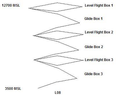
Figure
3 – N4975F Multi-Layered Glide Box Measurement Flight Path
For each leg of a glide box it’s important to
stabilize the aircraft at the same IAS and new heading after each turn before
recording the starting altitude and time. During the box leg, measure the GPS
ground speed. At the end of the box leg, record the altitude and time again.
Longer times in a leg result in more reliable data provided IAS and heading
(and therefore TAS) are crisply maintained.
The time-weight averaged level flight box and
glide box GPS measurement data and derived calculated values are compiled in
Table 3. The winds determined for the level flight boxes provide a cross-check
of the glide box winds, and were determined overall to be 217o +/–
20o and 20+/– 3 KTS at all altitudes measured, including glide
boxes. Final values for the glide ratio of N4975F at various altitudes for IAS
Vg = 62 KTS are determined by dividing TAS by FPM descent rate, and summarized
in Conclusions Table 5.
|
|
||||||||||||||||||||||||||||||||||||||||||||||||||||||||||||||||||||
|
Level Flight |
|||||||||||||||||||||||||||||||||||||||||||||||||||||||||||||||||||||
|
|
|
||||||||||||||||||||||||||||||||||||||||||||||||||||||||||||||||||||
|
|
||||||||||||||||||||||||||||||||||||||||||||||||||||||||||||||||||||
|
Glide |
|||||||||||||||||||||||||||||||||||||||||||||||||||||||||||||||||||||
|
|
|
||||||||||||||||||||||||||||||||||||||||||||||||||||||||||||||||||||
|
|
||||||||||||||||||||||||||||||||||||||||||||||||||||||||||||||||||||
|
Level Flight |
|||||||||||||||||||||||||||||||||||||||||||||||||||||||||||||||||||||
|
|
|
||||||||||||||||||||||||||||||||||||||||||||||||||||||||||||||||||||
|
|
||||||||||||||||||||||||||||||||||||||||||||||||||||||||||||||||||||
|
Glide |
|||||||||||||||||||||||||||||||||||||||||||||||||||||||||||||||||||||
|
Table
3 – N4975F Level Flight and Glide Boxes |
|||||||||||||||||||||||||||||||||||||||||||||||||||||||||||||||||||||
Conclusions
The two demonstrated GPS data-derived glide ratio measurement
methods performed well. I confirmed
better than reference glides using mathematical reductions of Garmin GPSMap 296 flight track
data for two apparently exterior-identical C-172Ns, N6360D and N4975F, at
similar gross weights and engine idle.
Between 8500 and 6500 MSL, the IAS Vg = 65 KTS
engine-idle glide ratio of N6360D was evaluated as 9.9 (1.6 NM per 1000 FT of
altitude), compared to the C-172N propeller wind-milling reference value of
9.1. In similar conditions, the IAS Vg =
62 KTS glide ratio of N4975F was evaluated as 11.0 (1.8 NM per 1000 FT of
altitude); its STC-modified POH omits glide ratio data for comparison.
|
|||||||||||||||||||||||||||||||||||
|
Table 4 – N6360D Engine-Idle Glide Ratios, GPS Derived |
|||||||||||||||||||||||||||||||||||
|
|
|||||||||||||||||||||||||||||||||||
|
|||||||||||||||||||||||||||||||||||
|
Table 5 – N4975F Engine-Idle Glide Ratios, GPS Derived |
|||||||||||||||||||||||||||||||||||
Drag factors that could explain observed
differences in glide ratios include weight, propeller pitch, idle RPM, airfoil
alterations, and paint condition or dirt.
Both aircraft have wheel pants, no obvious major external feature
differences, new or excellent paint, and were recently washed. N4975F has a slightly forward CG due to its
heavier engine, a different propeller, and a slightly higher idle RPM [5]. Note that the second glide of each aircraft
demonstrates bias from an engine ‘clearing’ (warming) acceleration.
Glide TAS and descent rate in N4975F decreased at
lower altitudes. An engine-idling
propeller has less drag than a wind-milling propeller, optimistically skewing
glide ratio above the reference value of 9.1 by up to +9% for N6360D and +20%
for N4975F.
References
1. Cessna Skyhawk Model 172N Information Manual (1979)
2. Wolfram Research MathWorld,
http://mathworld.wolfram.com/Parallelogram.html
(2006)
3. Wolfram Research MathWorld,
http://mathworld.wolfram.com/LawofCosines.html
(2006)
4. http://www.csgnetwork.com/tasgpscalc.html online tool for GPS TAS/wind calculations (
5. N4975F STC-Modified POH (2001)
6. G7ToWin GPS Data Tool, http://www.gpsinformation.org/ronh/
(
7. Advanced
Pilot’s Flight Manual (FAA AC 61-21A), p7. (Kershner, 1980)
8. MS Excel GPS data reduction spreadsheet, email scott@scottkurowski.com
(2006)
Disclaimer
Your results
may differ. Do not use this demonstration data or results for your flight
planning.
Acknowledgements
This
was a really fun project. Special thanks
to my data-recording friends, Mark Beaulieu and Dennis Williams. Thanks also to reviewers CFI Rod “Navy
Physics” Gibson, CFI/Plus One Safety Officer Bob Agresto,
CFI/Plus One Founder/Director Gus Schwartz, CFI/Plus One MYF Operations
Officer/Director Dave Eby, Plus
One President/Director Don Chadwick. Any
errors are my own. No airplanes were harmed in the making of this document.